Rather than adding a spur to a ring main to provide an additional socket outlet, it may be advantageous to extend the ring.
1. Plan for the new socket outlet
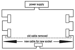
As you can see in the digram, this is done by inserting a longer length of cable between two of the sockets on the existing ring, allowing it to be routed and connected to the new socket on the way.
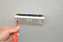
2. Switch off the power at the consumer unit for the circuit concerned. If you have removable fuses at your consumer unit, switch off the power at the consumer unit and remove the fuse for this circuit.
3. Establish the route taken by the ring main and decide upon the two sockets between which it is best to extend.
Adding the new cable
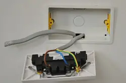
4. Fit the new socket box at the required position. The method for doing this will depend on whether it is a Surface Mounted Box, Flush Metal Box, or Plasterboard Box.
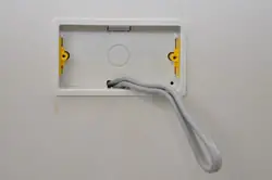
5. Lay cable from the first socket, taking it to the new socket position along the way, and on to the second socket. Remember to allow sufficient cable at the position of the new socket for making connections.
6. Cut the new cable at this point.
7. Strip both the new cable ends ready for connection. See our Cable Stripping Guide for detailed information on this.
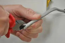
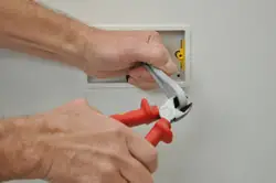
8. Cut through the outer sheath of the cable carefully using a pair of side cutters. Be sure not to cut into the insulation of the conductors.
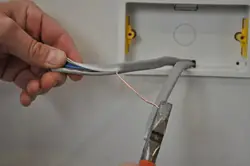
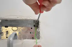
9. Peel back the sheath to reveal the conductors and grip the end of the bare earth conductor with a pair of pliers. Draw the wire back through the sheath like a cheese wire.
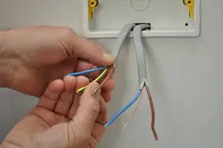
10. Insulate the earth conductors using the separately sold green and yellow sleeving. This should be cut to length and fed over the conductor so that about 1/2″ is left exposed at the end.
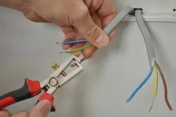
11. Separate the conductors and trim the insulation of each back by about 1/2″ with wire strippers.
Connecting the cables to the new socket outlet
12. Do not twist conductors together before inserting them into the connection as this may damage them and can also cause problems when testing circuits.
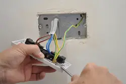
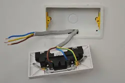
13. Slacken the screw of the appropriate connection terminal. Insert the brown (old cable colour = red), live conductors into the hole in the terminal marked ‘L’.
14. Ensure that the conductor is fully housed and that there is no exposed wire showing. Fasten the screw and make sure the wire is firmly secured.
15. Repeat the process for the blue (old cable colour = black), neutral conductors, fixing them in the terminal marked ‘N’.
16. Repeat the process for the green/yellow sleeved earth conductors fixing them to the terminal marked with the earth symbol.
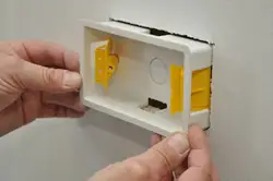
Metal Boxes Only
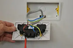
17. If you have a metal box like the one shown here, an earth tail may be required. One must be fitted between a socket outlet and metal back box where both socket fixing lugs are adjustable. If this is what you have, cut a suitable length of the earth conductor from some cable of the same size as that used for the circuit. Sleeve this with green and yellow sleeving allowing ½” conductor to be exposed at either end.
18. Connect one end of this earth tail to the earth terminal provided at the back of the metal mounting box.
19. Connect the other end of this earth tail with the earth conductors secured to the terminal marked with the earth symbol on the socket outlet.
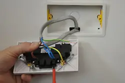
Fixing the socket outlet

20. Double check that all your connections are to the correct terminals, and securely fastened.
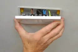
21. Carefully push the face plate back, gently folding the cables as you go, so that they sit neatly into the box.
22. Fasten the face plate with its retaining screws. Tighten the screws alternately to draw the plate back evenly.
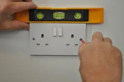
23. As you tighten these, ensure that the face is level. One or both of the screw mountings will have allowance for a small amount of vertical adjustment which assists with this.
Connecting the cables at both original sockets
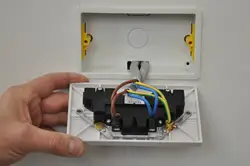
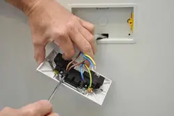
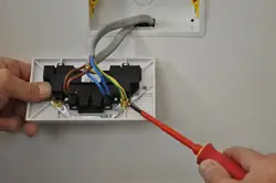
24. Working on one at a time, remove the face plates of the two sockets between which you are extending the ring main. Slacken the retaining screws and ease the socket outlet away from the wall.
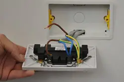
25. Establish which cable is the original one travelling between your two sockets and release it’s conductors.
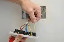
26. With the three conductors (Live, Neutral, and Earth) of the original cable released, the cable can be removed.
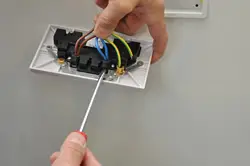
27. There should now be room to feed one end of your new cable into each of the boxes where you just removed the old one.
28. If not, remove one of the other blanking plates in the box to provide entry for the new cable. For metal boxes you will also need to fit a rubber grommet to the new entry hole. Feed the cable in so that there is sufficient to allow for connection.
29. Strip and prepare the ends of the new cable ready for connection. Protect the exposed earth conductor with green/yellow sleeving.
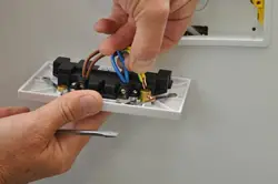
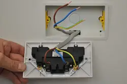
30. Taking the conductors of the new cable, one at a time, insert each alongside the corresponding one from the remaining original cable. Fasten the screw and make sure the wires are firmly secured.
31. Two brown (old cable colour = red) conductors connect to the terminal marked live (‘L’).
32. Two blue (old cable colour = black) conductors connect to the terminal marked neutral (‘N’).
33. Two green and yellow conductors connect to the terminal marked earth (earth symbol).
34. If these original sockets are mounted in metal boxes where both socket fixing lugs are adjustable there will be an earth tail between the earth terminal on the socket outlet and the earth terminal at the back of the metal box. Ensure that this earth tail is connected back in with the other earth conductors from each of the ring main cables
35. Tighten the screw of each terminal ensuring that the conductors are firmly held and that the insulated part of each butts right up to the terminal. Fixing the original socket outlets.
Fixing the original socket outlets
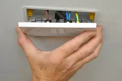
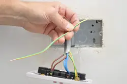
36. Double check your connections at both these sockets, and ease the face plates back to the boxes folding the cables carefully as you do so.
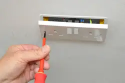
37. Re fix the retaining screws, tightening them alternately to draw the fascias back evenly against the surface.
38. As you tighten these, ensure that the face is level. One or both of the screw mountings will have allowance for a small amount of vertical adjustment which assists with this.
39. Once you are sure that all work has been completed correctly, switch the power back on at the consumer unit. In the case of removable fuses, replace the fuse for the circuit, and switch the power back on. Check your sockets to ensure they are working properly.